


No part of this publication may be reproduced, or transmitted, or stored, in any form or by any means, electronic,
mechanical, photocopying, recording, or otherwise, without the prior written permission of SheetMetalWorkBook.com, Sixth
Edition Reformatted for Internet, ©2012 SheetMetalWorkBook.com


Please Donate if
you find this site
helpful.
Thank-You!
Reliefs


Another
notch
which
we
will
call
a
relief
notch
is
set
back
(relieved)
a
certain
dimension
from
the
edge.
This
is
to
keep
the
material
from
fracturing
while
forming
the
metal.
Normally
that
dimension
is
called
out
on
the
blueprint.
Sometimes
this
notch
is
used
for
parts
with
a
large
bend
radius.
The
previous
notches
can
be
used
with
a
large
bend
radius
if
a
relief
hole
or
slot
is
used
in
the
corner
(see
Bend
Reliefs).
If
no
relief
distance
is
called
out
on
the
print
and
you
are
using
a
large
bend
radius
with
this
type
of
notch
then
to
be
safe
use
a
minimum
distance
of
the
material
+ the bend radius.
It
is
possible
to
see
a
variation
or
combination
of
some
or
all
of
these
notches
on
the
same part.
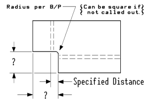
Below
is
an
illustration
of
a
corner
to
corner
with
relief
notch
combination
for
a
large
bend
radius.
If
depth
or
specified
distance
is
not
called
out
on
the
print
then
minimum
distance
would
be
material
thickness
plus
bend
radius.
The
two
distances
are
normally
the
same
dimension
but
can
be
different.


Flange - B.D. + Distance = ?
D1 = Flange - B.D. + Specified Dis.
D2 = Flange - B.D + Mat. Thk.
D3 = Flange - Depth
D4 = Depth - B.D. + Specified Dis.